
Gutter Takeoff: Runs, Downspouts, Fittings, and a Roof-Edge Map
Create a useful gutter material list from the roof edges that actually drain into the system, then leave hydraulic capacity, overflow paths, and local requirements to the project design.
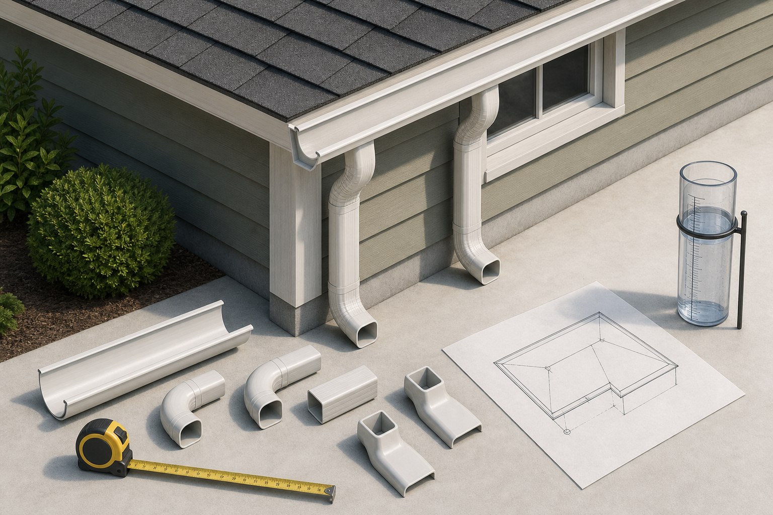
A gutter takeoff is more useful than a perimeter measurement because a building perimeter includes edges that may not collect roof runoff. A material list should begin with the roof planes, eaves, valleys, corners, and discharge locations that are actually part of the planned system. Our Gutter Calculator can organize lengths and component counts; it does not determine hydraulic capacity, roof drainage design, overflow routing, structural attachment, or compliance with local requirements.
Do not size gutters from length alone. Rainfall, contributing roof area, roof geometry, system profile, outlet capacity, slope, debris, overflow paths, and local rules can all affect a suitable design. Use a material takeoff only after the system concept is defined.
Make a roof-edge drainage map
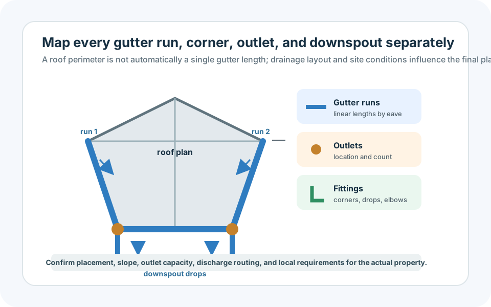
Start with a simple plan of the roof. Draw the ridge lines, valleys, eaves, rakes, dormers, porch roofs, and any roof plane that drains toward another roof or into a gutter. Then mark the edges that will receive gutters and the intended direction of flow. The map should show where a run begins, where it ends, and where water leaves through an outlet and downspout.
This is important because a long gable rake may have no gutter while a short lower-roof eave may receive water from a much larger upper roof. A plan that simply says measure the house
can miss both cases. Label the runs A, B, C, and so on, and write the contributing roof areas or planes next to them. The area note does not size the system by itself, but it makes a later design review possible.
Walk the exterior if you can. Confirm that a planned downspout does not block a door, conflict with a walk, discharge against a foundation, cross a driveway, or create a visible trip or ice hazard. Also record obstructions such as chimneys, roof transitions, wall projections, and existing drain connections. Those details often add fittings or require a different discharge plan.
Measure gutter length by run
For each labeled run, measure the finished horizontal gutter path along the fascia or planned mounting line. Keep corners and separate roof levels distinct. Do not subtract a downspout outlet from the gutter length; an outlet is a component installed within the run, not a gap in the run.
Example: a front eave run is 32 ft, a side porch run is 14 ft, and a rear roof has two separate 20 ft runs. The material length before product-size rounding is 86 ft. A supplier may sell continuous material, fixed lengths, or preformed sections. Record the purchase format because it affects seams, cut-offs, and the number of connectors.
At this point, compare the roof sketch with the measurement list. Every marked gutter edge should appear once; no roof edge should appear twice. This simple reconciliation catches more mistakes than adding a large unexplained percentage at the end.
Count components separately from footage
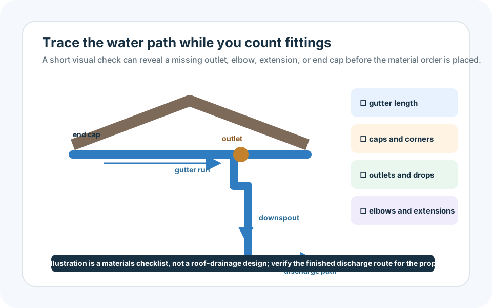
A complete gutter takeoff contains parts as well as linear length. The exact names vary by system and material, but the planning list often includes ends, inside and outside corners, outlets, drop tubes, downspout lengths, elbows, straps or hangers, connectors, sealant or fasteners specified by the manufacturer, and discharge extensions or connections.
| Component | How to count it | What to verify |
|---|---|---|
| Gutter run | Measured length on each mapped eave | Product length, seams, and corner layout |
| End cap | One at each open run end as applicable | Left/right orientation and system compatibility |
| Inside/outside corner | One for each planned directional change | Actual corner angle and manufacturer component |
| Outlet and downspout | One per planned collection point | Capacity, path, mounting, and discharge location |
| Elbows and extensions | From the actual vertical and horizontal route | Clearance from walls, walks, and drainage features |
Count a downspout as a routed assembly, not merely a number of vertical feet. A downspout that has to turn around a porch beam, reach a buried connection, or discharge away from the wall may use different parts than a straight drop. Sketch the route and count its fittings from the sketch.
Use local precipitation data as design input, not as a copied rule
Gutters exist to manage rainfall from roof surfaces. NOAA's Atlas 14 service provides official precipitation-frequency information for supported U.S. locations, while the U.S. Geological Survey explains the broader precipitation context. Those sources are valuable when a qualified project process needs local rainfall information, but they do not turn a generic online material calculator into a complete hydraulic design.
Do not choose the number of downspouts from a universal feet-per-downspout formula unless the responsible project standard, manufacturer guidance, or qualified designer has provided that rule for the actual system. The capacity of a run can be affected by roof area, rainfall intensity, gutter profile, slope, outlet geometry, downspout size, elbows, debris, and discharge conditions. Keep the selected number of outlets as a documented design input, then count the material needed to build it.
Plan discharge before ordering extensions
The gutter's job is not complete at the bottom elbow. The project needs a deliberate place for water to go. On the takeoff, show every discharge point and note whether it uses a surface extension, splash block, leader connection, rain barrel arrangement, swale, or another documented drainage feature. Do not assume that moving water a short distance from a wall prevents problems at the walk, neighbor's property, foundation, or low point.
The USDA NRCS urban-agriculture material is a useful reminder that water-management work is connected to site conditions. Local stormwater, plumbing, building, and property rules may apply to collection or discharge systems. A material list cannot determine where runoff is legally or safely allowed to go. If drainage crosses a sidewalk, approaches a retaining wall, enters a public system, or affects adjacent property, obtain project-specific direction.
Use visible allowances instead of an inflated total
There can be legitimate material extras: cut-offs for sectional systems, a spare elbow, continuous-run trimming, or a supplier's package quantity. Add them as a specific line with a reason. For example, two additional 10 ft pieces for cut plan and stock length rounding
is more meaningful than silently adding 15 percent to all components.
Avoid adding an allowance to resolve a design uncertainty. If the roof edge count, outlet layout, or discharge route is unknown, the correct response is to mark the estimate preliminary. More length will not correct an outlet in the wrong location.
Final review: follow water from every roof plane to a discharge point
Before purchasing, trace every roof plane on the sketch. Where does its water land? Does it enter a marked gutter run? Which outlet serves that run? Where does the downspout travel, and where does it discharge? Then reconcile that path with the order: gutter footage, corners, end caps, outlets, downspout sections, elbows, mounting hardware, and discharge parts should each have a source on the drawing.
Finally, consult the current installation instructions for the selected material. They control compatible components, fastening, support spacing, sealant, expansion, and other installation details. This guide is intentionally a takeoff method. It gives the installer or supplier a readable inventory, while leaving roof drainage, structural attachment, and water-management design to the project requirements and qualified professionals.
Sources and assumptions
These links support the specific material, product, or reference points used in this guide. Local conditions and supplier specifications can still vary.
- USDA NRCS: Urban Agriculture Handbook Public planning reference that reinforces the need to consider drainage and site conditions as part of water-management work.
- NOAA Atlas 14 Precipitation Frequency Data Server Official source for location-specific precipitation-frequency information in supported U.S. areas; capacity decisions require project-specific interpretation.
- U.S. Geological Survey: Rain and Precipitation Background on precipitation and the water cycle; it is not a gutter sizing table.