
Rebar Grid Takeoff: Spacing, Laps, Tie Wire, and Bar Schedules
Turn an approved reinforcing drawing into a traceable rebar takeoff by counting bars by direction, using specified spacing and laps, and listing chairs, ties, hooks, bends, and stock lengths separately.
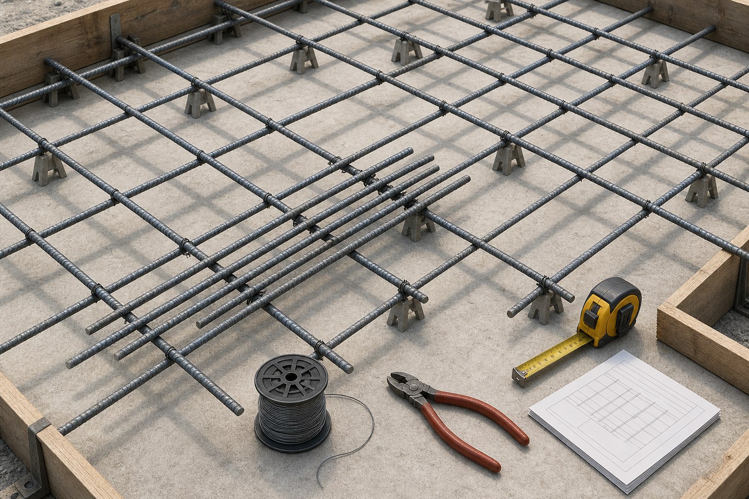
A reinforcing-steel takeoff converts an approved drawing into an order and placement worksheet. It should preserve the drawing's bar marks, size, grade or coating, direction, spacing, cut length, bends, hooks, lap locations, cover, supports, and notes. Our Rebar Calculator can help with count and length arithmetic, but it cannot select the reinforcing, determine a lap length, design a slab or footing, or confirm that bars are placed correctly.
Rebar is structural reinforcement, not a generic grid. Bar size, grade, spacing, cover, development, laps, hooks, bends, welding restrictions, coating, chairs, and placement sequence come from the project documents and applicable code. Never replace a specified detail with a calculator default.
Read the reinforcing drawing before counting steel
Collect the plan, sections, details, general notes, and bar schedule that apply to the pour. A plan may show bars in two directions, but a section can reveal extra top bars, thickened edges, dowels, stirrups, hooks, chairs, or a different cover condition. Record the drawing revision and every bar mark before entering numbers into a worksheet.
For each mark, make a row with the specified bar designation, quantity, direction, spacing or stated count, shape, cut length, lap or splice note, coating, and location. A bar with the same diameter can still be a different line item if it has a different shape, length, location, coating, or bar mark. The CRSI bar-identification reference linked below explains why identification matters; the schedule and drawings remain the controlling source for a project.
| Worksheet field | Example of what it records | Why it matters |
|---|---|---|
| Bar mark | Drawing's unique identifier | Keeps shapes and locations traceable |
| Size and material | Specified bar size, grade, coating | Not interchangeable by appearance |
| Location and direction | Bottom east-west grid or top strip | Prevents two layers from being merged |
| Count and cut length | Actual bars and fabricated length | Drives linear footage and stock planning |
| Lap, hook, and bend note | Exact detail reference | Changes the fabricated bar length |
Count a simple grid one direction at a time
For a rectangular approved grid, calculate the bar positions perpendicular to the bar direction. If bars run along the 20 ft dimension and are spaced across a 12 ft dimension, use the 12 ft dimension to count positions. Do not invert the directions. Use the stated spacing, then make sure the drawing's edge bar, cover, and offset requirements are included.
Many people add one bar after dividing by the spacing because positions include both sides of a sequence. That can be a useful check, but it is not a substitute for the drawing. Edge cover, a centered layout, a termination zone, or a stated count can change the answer. Draw the first and last bar positions on the plan and count the actual bars, not only the intervals.
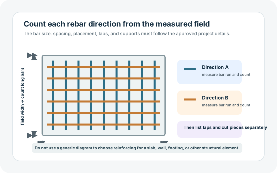
Repeat independently for the bars in the perpendicular direction. Then add any perimeter, thickened-edge, opening, strip, top-mat, or local reinforcing that the drawings specify. Keep a separate row for each; a slab that appears to have one grid can contain several different reinforcing conditions.
Use cut length, not just plan length
A plan line is rarely enough information to order a fabricated bar. The cut length may include specified hooks, bends, extensions, development length, laps, or terminations. Do not take a generic lap amount from a website or another job. Lap and development lengths depend on the design, bar size, concrete, coating, confinement, location, and other conditions. Use the exact detail or bar schedule.
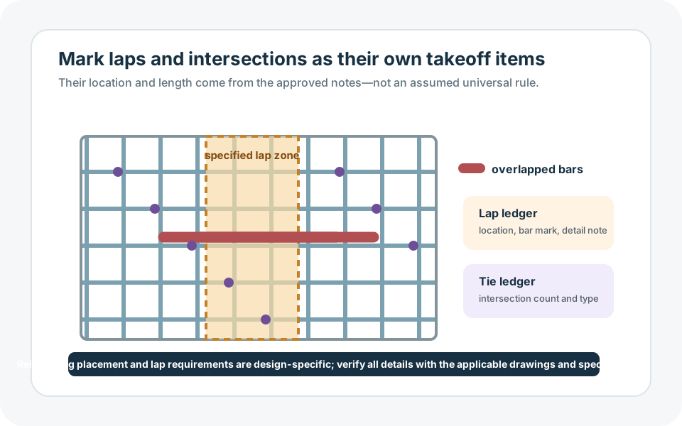
When a long run exceeds available stock length, mark each splice location shown or permitted by the plans. Add the specified lap to the bar pieces only where the detail calls for it. Do not make every bar longer by one arbitrary lap. A staggered splice layout, a no-splice zone, or a fabricated bar can change the count and length significantly.
After calculating linear length, decide whether the supplier will furnish stock bars or fabricated pieces. Stock-length optimization is an ordering exercise; it must not move a splice or change a bend that is specified in the reinforcing design. Ask the supplier for available lengths and fabrication lead time, then compare the proposed stock plan against the schedule.
Count ties and supports from a placement plan
Tie wire is used to hold reinforcing in its intended position during placement; it is not a replacement for specified support, cover, or placement requirements. The drawing or placing plan should identify whether every intersection, alternate intersections, perimeter intersections, laps, and special zones are tied. Count the indicated intersections and add the specified tie type or wire package coverage. Do not state an exact number of tie-wire coils without a product, tie pattern, and handling allowance.
Chairs, bolsters, dobies, spacers, or other supports should be scheduled by the placement plan and the selected support system. Their type and spacing influence cover and stability. A bar grid counted on paper can still be incorrectly placed if it is not supported at the required elevation. Record support rows separately from rebar weight or linear footage.
Openings, edges, and two-layer mats need their own rows
Do not subtract an opening by area and assume the reinforcing disappears. An opening may terminate bars, require bars around the perimeter, create extra diagonal or trimming bars, or change the top and bottom mat details. Mark the opening on the plan and follow the reinforcing detail. Edges, grade beams, footings, columns, and thickened sections can likewise contain bar marks that are not part of the main grid.
For two-layer reinforcement, keep the top and bottom mats separate even if the bar sizes and spacing happen to match. Their supports, laps, sequencing, and cut lengths can differ. Use the Concrete Calculator to estimate concrete volume only after the concrete geometry is known; do not derive the reinforcement layout from the concrete volume.
Make an audit-friendly bar schedule
The final takeoff should let someone check every quantity against the drawings. Include bar mark, location, size, coating or grade, shape, cut length, number of pieces, total length, requested stock or fabrication method, drawing reference, and notes about laps, hooks, supports, or sequencing. Put tie wire, chairs, spacers, couplers, and other accessories in their own section.
Before release, compare the schedule with every plan and section. Check for bars at openings, top and bottom layers, edge conditions, dowels, laps, hooks, and any notes that refer to another detail sheet. Ask the reinforcing supplier to verify fabrication notation and available stock lengths. If the plan is revised, rebuild the affected rows rather than carrying a rounded weight from an earlier drawing.
What this guide cannot authorize
This guide cannot decide a rebar size, spacing, cover, lap, hook, bend, splice location, bar grade, weld, support system, or placement sequence. It cannot approve a concrete element, replace inspection, or determine whether a field change is safe. Treat it as a method for preserving the approved reinforcing information in a clearer material list. The responsible design and construction professionals must resolve questions before concrete is placed.
A useful rebar takeoff is intentionally specific: it shows exactly where every number came from and makes unknown details visible. That protects the order from the common error of turning a structural drawing into a generic square-grid calculation.
Sources and assumptions
These links support the specific material, product, or reference points used in this guide. Local conditions and supplier specifications can still vary.
- Concrete Reinforcing Steel Institute: Bar Identification Explains reinforcing-bar identification. Use the reinforcing drawings and bar schedule for the required grade, size, coating, and fabrication.
- Concrete Reinforcing Steel Institute: Placing Bars Educational reference for reinforcing placement. Spacing, cover, laps, supports, and tying must follow the project documents and applicable code.