
Rebar Calculator
Turn approved reinforcing inputs into a transparent count, linear-foot, planning-weight, and budget worksheet. This tool does not select rebar size, spacing, cover, splice length, or structural detailing.
Example Projects
Concrete Patio Slab
15' × 12' slab · #3 rebar @ 12" O.C.
Residential Driveway
40' × 20' slab · #4 rebar @ 18" O.C.
House Foundation Slab
60' × 40' slab · #5 rebar @ 16" O.C. (Double Mat)
Foundation Trench Footing
100' long · 3 long bars (#4) + transverse @ 12"
Deck Footing Beam
50' long · 2 long bars (#3) · No ties
Retaining Wall
50' × 6' wall · #5 rebar @ 12" vert & horiz
Basement Wall
120' × 8' wall · #4 rebar @ 16"/18" (Double Mat)
Round Support Pier
12" Dia × 10' high · 4 vert (#4) + #3 ties @ 8"
Structural Column
18"×18" × 15' high · 8 vert (#6) + #3 ties @ 6"
Custom Rebar Mat
20' × 20' · Custom grid: 15 rows × 15 columns
Project Settings View Results
Rebar Estimate
View Calculation Details
| Layout Stats | 0 rows × 0 columns (0 intersections) |
| Length-direction Pieces | 0 |
| Width-direction Pieces | 0 |
Grid Calculations Breakdown:
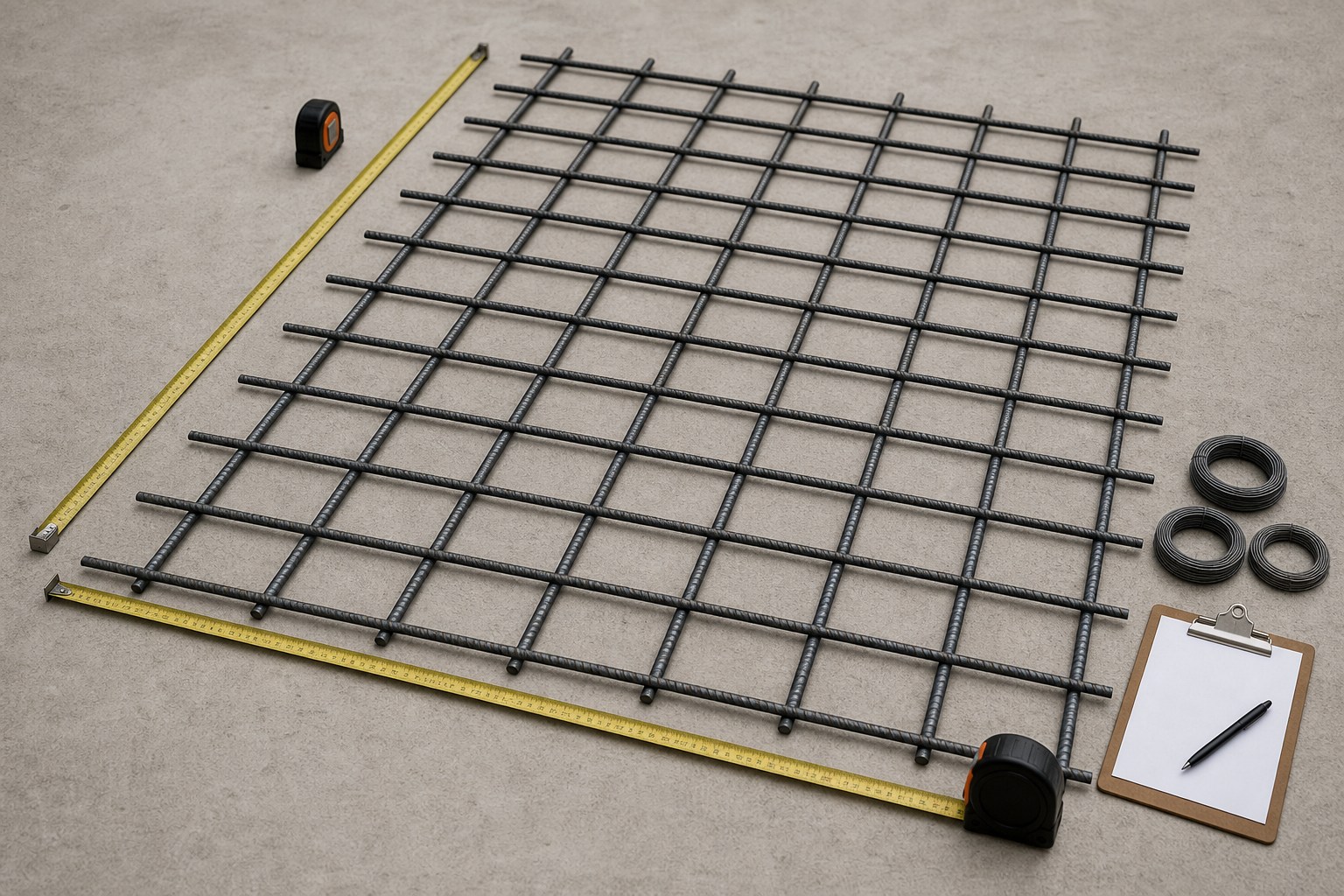
Check the method before you use the estimate
This page documents the formula, assumptions, and any specific external sources used for this tool.
See the methodPlanning estimate What this result can and cannot tell you
Material-planning worksheet only. Use the approved structural drawings, bar schedule, specifications, applicable code, supplier fabrication information, and responsible design and construction professionals for every decision about reinforcing steel.
How the Rebar Calculator works
These notes describe the calculation used on this page and the assumptions that can change a real-world result.
For a simple grid: usable dimension = entered dimension - (2 × entered cover); positions = ceil(cross dimension ÷ entered spacing) + 1; planning linear feet = the two directional runs, adjusted only by the entered splice and waste inputs; planning weight = displayed linear feet × selected bar weight per foot.
Assumptions on this page
- Every size, spacing, cover, bar count, layer, splice or lap input, stock length, and waste allowance must come from the approved project documents or a documented supplier decision; the calculator does not select them.
- The grid arithmetic assumes a simple, uniform rectangular or linear condition. Openings, corners, thickened zones, bends, hooks, dowels, top mats, special bars, and other bar marks need their own documented lines.
- The stock-piece result is a preliminary material-planning result. It does not create a fabrication schedule, optimize cuts, move splices, or replace the specified bar schedule.
- Planning weight is a conversion from displayed linear feet and a selected bar weight. Keep different bar sizes, shapes, coatings, ties, couplers, supports, and accessories separate instead of combining them into one generic line.
- Chair, spacer, and tie-wire displays are provisional quantity aids only. Their type, spacing, tie pattern, and placement must follow the project documents and selected support system.
- This calculator is not structural design, code compliance, fabrication approval, inspection, or safe-placement guidance.
Sources used on this page
- Concrete Reinforcing Steel Institute: Placing Bars Explains why placement, supports, cover, and related details must follow the project requirements rather than a generic grid calculation.
- Concrete Reinforcing Steel Institute: Splicing Bars Provides context for treating splice information as a project-specific reinforcing detail, not a universal calculator setting.
- Concrete Reinforcing Steel Institute: Bar Identification Supports keeping the specified bar identification, size, grade, coating, and bar mark visible in an order worksheet.
Everything behind the Rebar Calculator
Formulas, reference charts, and detailed answers — expand any section you need.
Keep the calculator result audit-ready
A useful output is one that another person can trace back to the documents. Keep the calculator total beside its input record rather than using it as a standalone purchase instruction.
| Worksheet field | What the calculator can organize | What must remain tied to the documents |
|---|---|---|
| Grid or bar count | Position arithmetic from the dimensions and entered spacing or count | Edge bars, offsets, openings, extra strips, and every non-uniform condition |
| Linear feet | Run lengths with the entered splice and waste inputs | Actual cut lengths, bends, hooks, stock optimization, and permitted splice locations |
| Planning weight | A conversion from the selected bar's weight per foot | Separate bar marks, tie sizes, coatings, fabricated shapes, couplers, and supplier weight schedule |
| Chairs and tie wire | Optional provisional display quantities | Support type, tie pattern, locations, cover control, and installation sequence |
| Cost | Arithmetic using the rates entered by the visitor | Current supplier quote, taxes, fabrication, delivery, lead time, and all project terms |
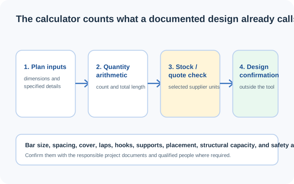
Use this calculator after the reinforcing has been specified
This page is a quantity worksheet, not a rebar design tool. It can organize lengths, grid positions, optional planning weight, and budget inputs after a project has already identified the relevant bar marks, sizes, directions, spacing or stated counts, cover, splice details, supports, and layers. Choosing Slab, Footing, Wall, Column, or Custom Grid changes the arithmetic on the screen; it does not establish what reinforcement the project needs.
That distinction prevents a common and costly mistake: treating a convenient calculator input as a construction instruction. The current drawing set, sections, details, notes, and bar schedule control. If they do not identify an input, keep it unresolved rather than filling it with a value from a previous job, a preset, or a generic online rule.
For a full drawing-to-order workflow, use the companion Rebar Grid Takeoff guide. This calculator page stays focused on how the tool turns already approved inputs into a checkable quantity result.
Read every input from a traceable source
Before entering numbers, make a short worksheet row for each bar mark or uniform grid. Record the drawing revision, location, direction, specified bar size and coating, spacing or stated count, cut length, cover note, lap or splice detail, stock or fabricated length, number of mats, and any related notes. A bar that looks similar can still be a different order item if its mark, shape, grade, coating, cut length, or location differs.
- Slab or custom grid: use the measured or drawn length and width, then enter only the specified spacing or counts.
- Footing: enter the stated longitudinal quantity and any transverse pattern from the detail; do not derive reinforcing from footing size alone.
- Wall: keep vertical and horizontal bar inputs distinct, and use separate rows when wall zones or mats differ.
- Column: use the project bar schedule for longitudinal bars and ties. The calculator's loop geometry is not a substitute for a specified tie shape, hook, or confinement detail.
The Concrete Reinforcing Steel Institute's placing-bars guidance provides useful context: reinforcing placement depends on the project requirements, including cover and supports.
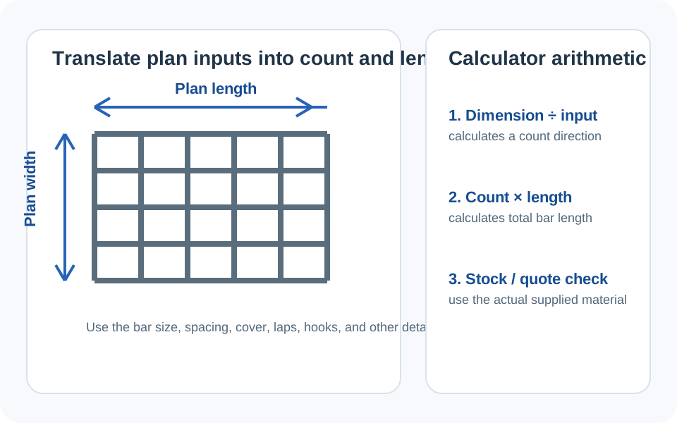
What the grid arithmetic actually does
For a simple slab or wall grid, the calculator first removes twice the entered cover from the relevant dimension. It then counts one bar direction from the usable dimension across the bars and the entered spacing. In simplified form:
It repeats that calculation for the perpendicular direction, calculates the run length in each direction, and applies only the splice and waste values supplied in the form. This is a helpful arithmetic check, not an instruction to use the selected cover, spacing, bar stock, or lap input.
Worked worksheet example: suppose an approved, simple one-mat rectangular layout identifies a 20 ft by 12 ft area, 3 in of cover, and 18 in spacing in both directions. The usable dimensions are 19.5 ft by 11.5 ft. The calculator's position arithmetic is 9 runs along the 19.5 ft direction and 14 runs along the 11.5 ft direction. Before any user-entered splice or waste allowance, the planning length is (9 × 19.5) + (14 × 11.5) = 336.5 linear ft. If the approved bar mark is #4, the displayed planning weight would use the tool's #4 weight factor of 0.668 lb/ft: about 224.8 lb.
The example demonstrates calculator arithmetic only. It does not say that those dimensions, cover, spacing, bar size, mat count, or absence of splices are suitable for any slab or other project.
Split non-uniform reinforcement into separate lines
Do not use one rectangle to hide an opening, a return, a thickened edge, a top mat, a change in bar mark, or a local reinforcing condition. The input geometry can be correct while the result is still incomplete because the drawing contains several different reinforcing rows. For each distinct condition, keep a separate calculator run or a separate manual line with its drawing reference.
The same rule applies across related tools. The Concrete Calculator estimates material volume after geometry is known; it does not determine the reinforcement. The Foundation Calculator can organize a quantity estimate, but it cannot establish footing or reinforcing design. Keeping those calculations separate makes an update easier to audit when the plans change.
Where calculator math stops
This tool cannot choose rebar size, grade, coating, spacing, cover, development length, lap or splice length, hook, bend, welding method, tie pattern, chair or spacer system, stock length, fabrication method, or placement sequence. It cannot determine whether a slab, footing, wall, or column is structurally adequate, and it cannot replace inspection or project-specific code review.
In particular, a displayed lap or chair quantity is never an authorization to change an approved detail. Use the relevant design documents and the responsible project parties before changing anything that affects reinforcing, concrete cover, formwork, excavation, or a pour sequence.
Final quantity and supplier check
- Confirm the drawing revision and every bar mark included in the worksheet.
- Check that each spacing, count, cover, splice value, and layer came from the correct plan, detail, or schedule.
- Compare net linear feet with separate lines for openings, top mats, corners, dowels, ties, and specialty bars.
- Ask the supplier to confirm fabrication notation, available lengths, coatings, and the current order format.
- Keep a note of the assumptions and re-run the affected row when the documents change.
If a calculator result or label is unclear, use the contact page to report the issue. The site team can review the tool behaviour, but structural and placement questions belong with the responsible project professionals.
Frequently Asked Questions
Does this Rebar Calculator choose the rebar size or spacing?
No. Enter bar size, spacing, counts, cover, laps, layers, and other reinforcing inputs only after they are specified for the project. The calculator organizes the arithmetic; it does not design reinforcing.
How does the calculator count bars in a simple grid?
For a uniform slab or wall grid, it subtracts the entered cover from both edges, divides the usable cross dimension by the entered spacing, rounds up, and adds one position. Repeat separately for both bar directions and compare the result with the actual drawn layout.
Is the lap splice value a recommendation?
No. A lap or splice value is a user input for quantity arithmetic. Use the project-specific reinforcing details and bar schedule; do not choose a lap length from a generic calculator or another job.
Why should openings and extra reinforcing be separate rows?
Openings, edges, thickened zones, and local details can change bar marks, directions, cut lengths, and quantities. A single average grid may miss those items, so calculate or list them separately from the main field reinforcement.
Can I use the displayed weight as a supplier purchase order?
Use it as a preliminary planning comparison only. A supplier order should follow the approved bar schedule and identify each bar mark, size, grade or coating, shape, cut length, quantity, and fabrication requirement.
Does the calculator determine chairs or tie wire?
No. The optional chair and tie-wire displays are provisional aids. Support type, support locations, tie pattern, cover, and placement requirements must come from the project documents and selected support system.
Can the column mode create a reinforcing schedule?
No. It can organize a simple quantity estimate from inputs you provide. Column bar counts, tie shapes, hooks, spacing, cover, confinement, splices, and fabrication must follow the approved structural documents.