
Retaining Wall Material Takeoff: Base, Drainage, Backfill, and Block Courses
Build a retaining-wall material estimate from an approved wall section and plan, keeping facing units, base material, drainage aggregate, pipe, backfill, caps, and geogrid as distinct quantities.
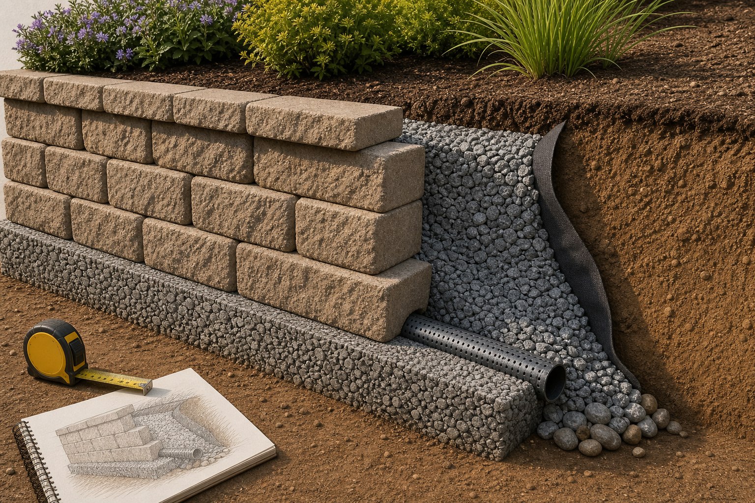
A retaining-wall material takeoff begins with an approved wall section and plan. The visible blocks are only one material zone. A complete estimate can also include excavation, leveling material, drainage aggregate, pipe and outlets, reinforced or select backfill, geogrid where specified, caps, corner units, and erosion-control or surface-drainage components. Our Retaining Wall Calculator can help organize preliminary facing and volume arithmetic. It does not design a retaining structure or determine the safe wall height, soil conditions, drainage system, reinforcement, setbacks, permits, or utility conflicts.
Retaining walls are not a generic landscaping quantity. Water, soil, slope, surcharge loads, nearby structures, utilities, wall geometry, product system, and local requirements can change the design. Do not use an area or block estimate to choose a wall system or begin excavation.
Read the wall as a section and a plan
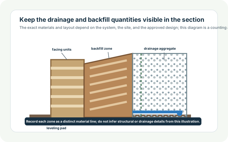
A section shows the vertical layers: finished grade, wall facing, base or leveling pad, drainage aggregate, pipe, backfill, and any reinforced zone. A plan shows the wall length, curves, corners, returns, steps, outlet locations, property or utility constraints, and delivery access. You need both. A straight-line wall length can estimate a row of facing units, but it cannot show a curve radius, stepped grade, return, drainage outlet, or material zone behind the wall.
Begin by recording the drawing revision and every dimension exactly as specified. Do not substitute a default base width, drainage zone width, embedment depth, geogrid length, or pipe location from another project. Those dimensions belong to the approved system and site conditions. If they are not known, list them as unresolved rather than creating a confident-looking quantity.
Measure facing units course by course
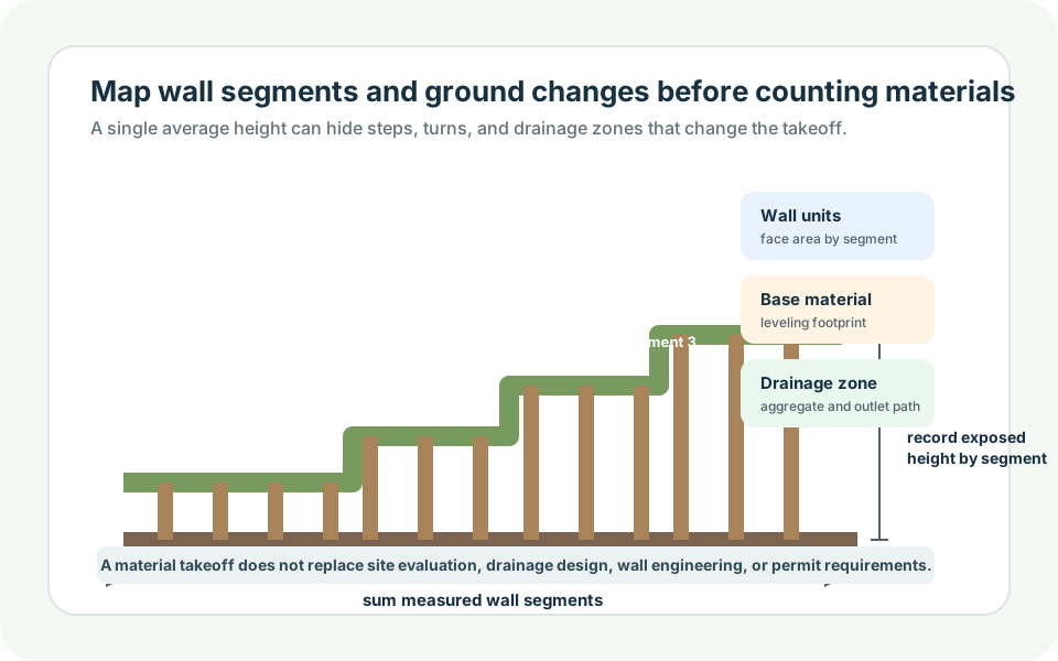
Split the wall into segments with a consistent height and plan geometry. A wall that steps up the slope should not be measured as one average-height rectangle. For each segment, record the finished exposed height, planned embedded portion if shown in the detail, block face dimensions, number of courses, and linear run. Then make a separate row for standard units, corner units, caps, cut units, and curves.
That area is a first-pass check, not the final block count. The final count should follow courses. Draw each course and count the actual units in the segment. Curves and corners can use different units or create more cuts; cap pieces may have different coverage than facing blocks. A stepped wall can gain extra cap runs and transitions that a simple overall area calculation hides.
Use the supplier's current unit coverage and the project layout to make the order. Do not assume units from different product lines are interchangeable, even when their face sizes appear similar. Interlocking geometry, setback, cap fit, and approved installation details may differ.
Calculate base, drainage, and backfill as separate volumes
Each material zone is usually a volume. Use the dimensions from the wall section and the length of the relevant wall segment. Convert all inputs to the same unit before multiplying. For a rectangular material prism:
Apply this independently to the specified base, drainage aggregate, and backfill zones. The width and depth can change near a step, curve, corner, outlet, or reinforced section. If a wall section calls for a tapered or irregular zone, break it into simple measurable shapes or use the geometry from the approved details. Do not hide different materials in one total labelled gravel.
| Material zone | Input from the project detail | Takeoff output |
|---|---|---|
| Facing blocks and caps | Course layout, unit coverage, curves, corners | Units by type |
| Base or leveling material | Specified width, depth, and wall run | Cubic yards or tons using supplier data |
| Drainage aggregate | Specified drainage-zone dimensions | Cubic yards or tons using supplier data |
| Drain pipe and outlets | Plan runs, fittings, and outlet locations | Linear feet and components |
| Backfill and reinforcement | Approved wall design and section | Separate volume or product schedule |
Use the Gravel Calculator or Cubic Yard Calculator to cross-check a known volume, but use the supplier's stated density when an order must be converted from cubic yards to tons. Different aggregate products, moisture conditions, and local materials can weigh differently.
Drainage is a material and routing problem
Water management is a central part of retaining-wall work. The drainage aggregate and pipe must lead to a discharge location or system that is actually shown and allowed for the site. Count pipe from the plan, then add the required fittings, cleanouts, outlets, sleeves, and protection only when they appear in the approved detail. A pipe length alone is not a drainage design.
Trace water on the drawing. Note roof downspouts, paved areas, upstream slopes, irrigation, seepage, and surface flow that might reach the wall. Do not direct water onto a neighbor's property, into an unsuitable location, or toward a structure simply because it shortens the pipe run. Site drainage is not something a generic calculator can approve. The Allan Block water-management guidance linked below is useful for understanding the topic, while the actual project needs its own documented solution.
Keep excavation separate from imported material
Excavation volume and imported base or aggregate quantities are not the same number. Excavation may include overdig for working room, unsuitable soil removal, grades, step transitions, and temporary safe access. Imported material is measured from the specified installed zones and may be ordered with a documented compaction or handling allowance. Do not assume the hole volume will equal the trucked-in aggregate volume.
List excavation as a separate operation with its own dimensions, slope or shoring requirements where applicable, spoil handling plan, and utility verification. Use the Excavation Calculator only as a volume worksheet after the excavation limits have been established. It cannot decide a safe trench or excavation method.
Plan for curves, steps, corners, and delivery
Curved walls may use a different setback pattern or unit arrangement. Inside and outside corners need their own count. Stepped walls can require extra base transitions, cap cuts, and drainage coordination. Record these as separate segments rather than applying one average yield across the entire wall. Photograph or sketch the proposed delivery path too: wall blocks, aggregate, and base material may be delivered by different vehicles and staged in different places.
For each segment, create a worksheet row: plan length, exposed height, courses, standard units, specialty units, cap length, base volume, drainage volume, pipe length, outlet components, and any specified geogrid or backfill material. This structured list makes a later design change traceable. If a wall is revised from straight to curved, you can see immediately which quantities must be recalculated.
Final checks before an order
Compare the takeoff with the selected system's current documents. Check unit dimensions and coverage, cap type, base and drainage material specification, pipe size and fittings, geogrid product and lengths if specified, and supplier packaging. Confirm the drawing shows how water reaches and leaves the drainage system. Confirm the wall system, height, slope conditions, loading, utilities, and permit path are resolved by the responsible project team.
Do not treat this guide as a structural, geotechnical, or hydraulic design. It is an audit-friendly material worksheet. Its value is that every material has a visible purpose and source dimension instead of being buried in a vague total.
Sources and assumptions
These links support the specific material, product, or reference points used in this guide. Local conditions and supplier specifications can still vary.
- Allan Block: Basic Installation Manufacturer installation guidance for its retaining-wall system. Use the selected system's current documents and project-specific approved design.
- Allan Block: Water Management Explains the importance of managing water in retaining-wall work. Drainage details and outlet locations must be confirmed for the actual site and system.